| Part 1: Introduction |
| Part 2: Preliminaries |
| Part 3: Camber measurement |
| Part 4: Toe measurement |
| Part 5: Calculate adjustments |
| Part 6: Front adjustments |
| Part 7: Rear adjustments |
In Part 1 I introduced a simple and accurate suspension alignment method for a Porsche 996. In this part I will get through some of the preliminaries. Part 3 will cover camber measurements, which are no different from how many other sources describe them.
Laser Holder Plate
We need a way to hold the laser levels very precisely against the wheel rim edges. Here is how I constructed mine.
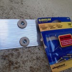
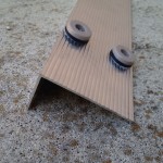
I bought an aluminum sill nosing, which is an inexpensive angle, and cut it to 24″ in length. I bought some screw-in furniture leg “sliders” (see photo below). These sliders are screwed to the plate with machine screws and will rest on the wheel rim edges to locate the plate correctly against the rim, and to separate the plate from the tire and, for some wheel designs, the wheel center. The sliders should be placed so their centers are on the wheel rim edges when the completed plate is placed on the wheel rim. In my case, with 18″ wheels, the slider centers were 19″ apart.
We don’t need to use these sliders; any hard, even surface that can be strongly attached to the plate and are extremely uniformly in thickness can be used, such as hard rubber adhesive “feet” or large adhesive silicone “dots.” They must be essentially incompressible, however, and shouldn’t scratch the rim. Any difference in heights translates directly to an error in toe, and there isn’t much tolerance to work with. A digital caliper is useful to check total height from the inside of the aluminum angle to the outside of the spacer; these height differences should not exceed 0.2 mm (which translates to a toe angle error of 1.4 minutes, about 1/4 of the total toe angle tolerance budget).
The importance of careful selection of parts and measurement to ensure precise matching of heights across all four contact points of the plate against the wheel rim can’t be overstated. This is a one-time effort, so allow some time to do it right.
Car Preparation
Standard preparation steps (from Porsche manual, and other bits of common sense) are:
- Fill gas tank
- Remove anything of significant weight from the passenger compartment and trunk that isn’t normally part of the car (yes, leave in the seats and spare tire); do not add weight to simulate a driver
- Ensure all suspension components are in excellent mechanical condition; excess play or wear will not provide a good result
- Have all the usual tools on hand (floor jack, jack stands, correct wrench sizes, etc.)
- Have the suspension alignment specifications for your specific model and suspension
- Torque specifications
- A drawing or photo of where the adjustments and lock nuts are, and for the rear, which is camber and which is toe!
Alignment specifications, torque specifications, and drawings of the suspension are very well done in the Bentley Service Manual among other sources.
Alignment specifications are available from a number of sources. I have included yet another copy here. Make sure you know what your suspension type is.
Level Floor
It is crucial that all four wheels be as level as possible. Actually it is acceptable for front and rear to be slightly off perfect level, but left and right of each pair must be as level as possible.
My garage is old and the floor is cracked and uneven. I used a bubble level and searched for four spots near the middle of the garage where left and right heights where wheels would be were very close to the same heights. If I couldn’t find locations that were exactly the same heights, I measured the difference and found a magazine or some newspapers to make up the difference and placed it over the lower spot. I marked the spots with tape and then permanent marker and noted the height required to bring the lower of each pair up the required distance. In my case I needed about a 3/16″ magazine under the right front tire.
The Laser Levels
The laser levels I have linked to in the Shopping List of Part 1 have two key attributes:
- They’re cheap ($18 at last check)
- They have a two-position laser selector that can either produce a beam like we’re all used to seeing, or a fanned-out line
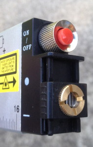
Here are two photos of the “business end” of the laser levels showing the beam selector. We will use one level in “beam” mode and the other in “line” mode.
Drive In
Now drive the car in slowly, gently braking so that the tires are right on top of the level markers. The steering wheel should be perfectly straight, even if that doesn’t result in the car moving straight (toe adjustment will fix that). Don’t set the emergency brake (use blocks gently placed by the tires if there is any slope).
The key right now is not to disturb the set of the suspension as it was when the car was carefully driven in — no additional settling or bumping, and especially not moving the steering wheel. The suspension as it was when it was driven in is exactly how we want to measure it.


