| Part 1: Introduction |
| Part 2: Preliminaries |
| Part 3: Camber measurement |
| Part 4: Toe measurement |
| Part 5: Calculate adjustments |
| Part 6: Front adjustments |
| Part 7: Rear adjustments |
Rear Adjustments: Camber and Toe
Very Accurate Adjustments are Required
Adjusting the rear toe is equally exacting as front toe, but we don’t have the very convenient ability to measure our adjustment using threads of the tie rod. Still, it is not difficult given a few techniques and simple tools. Like for the front toe, this adjustment is exacting for two reasons:
- The adjustment affects the location of a ball joint only 6″ from its axis of rotation (the distance of the toe control arm from the lower control arm which is also the camber adjustment)
- The allowed variation of the toe specification is +/- 5 minutes, or +/- 0.083 degree
Combining these, we see that the entire 5 minute variation occurs with only 1.1 millimeters of adjustment of the toe control arm. We would like to be more accurate than that, so let’s set a goal of being able to make 0.2 mm adjustments with reasonable confidence. We probably can’t be quite as accurate as for the front toe.
While the rear camber adjustment is not nearly as touchy, we must make the camber adjustment just as accurately as the toe adjustment. This is because the camber adjustment affects the toe almost directly. If we are “sloppy” and make our camber adjustment to within 1 mm, we easily satisfy the camber variation, but introduced a toe error that is already the whole variation allowed by the Porsche spec.
The whole premise of this alignment method is that we don’t iterate. We made the measurements, calculated the adjustments, now we must make exactly those adjustments. The camber adjustment must be made to the same accuracy as the toe adjustment precision, otherwise the toe will be off. Luckily it isn’t actually very hard.
Tools Required
- 18 mm (eccentric bolt nut) and 19 mm (eccentric bolt) combo wrenches
- Spring clamp with 2″ jaw
- Metal angle (scrounge around for something with at least 3/4″ sides and at least 2-3″ long)
- Set of feeler gauges
How We Will Make Very Accurate Adjustments
To achieve the accuracy we need for both camber and toe, we will use a set of feeler gauges and a spring clamp. We will attach the spring clamp to the control rod, either camber or toe, that moves when we turn the eccentric bolt for the adjustment, and use the feeler gauge between the clamp and a non-moving reference surface holding the eccentric bolt to see when we’ve made the right amount of adjustment.
Jack the Rear of the Car Up and Remove Rear Wheels
We will need to jack the rear of the car up and remove the rear wheels. Of course, place the car on sturdy jack stands. Make sure the location of the jack stands doesn’t interfere with adjusting the two eccentric bolts! (I’ve done this before.)
Familiarization
With the rear jacked up and supported on jack stands, familiarize yourself with the locations of the eccentric bolts and their nuts, and how you will get to the nut and bolt head with the wrenches. Find the toe and lower control arms that will move when you turn the eccentric bolts. Figure our which way to turn the eccentric bolts to achieve the right direction of movement of the arms.
Camber Adjustment
Use the 19 mm wrench to loosen the camber eccentric bolt’s nut. It should not need to be finger loose, in fact it should still have some torque on it so that the eccentric bolt is still held in its current position. I’ve found that less than half a turn from full torqued position is plenty.
Now we will set the clamp to guide the adjustment. There are two ways we will set the clamp, depending on whether the arm needs to move in (negative adjustment on the spreadsheet), or move out (positive adjustment on the spreadsheet).
Positive Camber Movement Amount
If the camber adjustment amount from the spreadsheet is positive, it means the arm must move outwards (toward outside of car). To measure how much the arm is moving, we will place the clamp on the arm snug against the suspension frame member that holds the eccentric bolt and adjust the eccentric bolt to make a gap appear. See the photos.
 Clamp attached to arm, snug against frame member, ready for positive (outward) movement. |
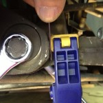 Eccentric bolt turned to push arm outward (to the right). Gap being measured with 3 feeler blades. |
Select a few blades from the feeler gauge set that add up to the distance the camber arm needs to move. Let’s say we need to move it 1.6 mm out. I can find three blades in my set of 0.50, 0.53, and 0.56 mm that add up to 1.59 mm. That is definitely good enough. Pull these three blades out and fold the rest back into the body of the gauge set.
Make sure the clamp is snug against the frame and start turning the eccentric bolt with the 18 mm wrench to push the arm outwards. It won’t take much, maybe 1/10 of a turn, until we see a gap appearing between the frame member and the clamp. Start feeling with the gauge blades while turning the eccentric bolt until the three blades (or however many you selected to add up to your adjustment distance) just snugly fit between the frame member and the clamp. Remove the feeler blades. Try turning the eccentric bolt back the other way a tiny touch and it should be difficult to get the blades back into the gap. Turn again back out so the blades again slide in between with some resistance.
Note that the clamp can be moved if the feeler blades are left in the gap and the eccentric bolt is turned back, pulling the arm in. This is a critical point: once the clamp moves, the adjustment reference is no longer right and we are left without knowing where exactly the adjustment is correct. Be sure that once the clamp is placed, it is not moved until the adjustment is done.
Now carefully tighten the nut, being very sure that the eccentric bolt is not turning. This nut has a torque spec of 74 ft-lb.
The adjustment is now done.
Negative Camber Movement Amount
If the camber movement distance is negative, the camber arm must move in, toward the center of the car, and into the suspension member holding the eccentric bolt. In this case we must place the clamp on the arm, exactly the distance it needs to move in from the suspension frame member, then turn the eccentric bolt to move the arm in until there is no gap between frame member surface and clamp remaining.
Actually we won’t quite do it this way, because getting to a “zero” distance runs the risk that we move the arm in too far and the clamp gets moved. Instead, let’s say we need to move the arm in by 1.6 mm (spreadsheet distance is -1.6 mm). We will choose feeler blades adding up to 1.6 mm but then we will add another blade in too, which can be any thickness.
Now we will place the clamp on the camber adjustment arm so that it is snugly squeezing all the blades we selected, including the added blade, against the frame member. Remove the blades. Turn the eccentric bolt carefully and slowly until the gap between clamp and frame member has almost but not quite disappeared (this is critical). When the gap is small, feel for the distance using the added feeler blade by itself. Adjust the eccentric bolt until just this one blade slides into the gap with some resistance.
Carefully tighten the nut, being very sure that the eccentric bolt is not turning. This nut has a torque spec of 74 ft-lb.
The adjustment is now done.
Toe Adjustment
The toe adjustment proceeds exactly like the camber adjustment. Note again whether the movement is positive (arm moves toward outside of car) or negative (arm moves toward center of car), and select the correct clamping and feeler gauge strategy as described above in the camber adjustment section.
The one wrinkle with the toe adjustment is that, depending on the tools being used, there may not be an obvious, easily accessible suspension frame surface to reference the clamp location to. To solve this problem I used the clamp to clamp a small metal angle piece to the arm, so that the angle piece sticks up vertically and becomes the reference against a convenient surface of the suspension frame member that holds the toe eccentric bolt. Some experimentation may be good to find the best approach. Again, it is critical that the arm location reference not move during adjustment, as it is the only reference point for the adjustment.
Alan
/ Mar 14, 2016But surely you are supposed to tighten the eccentric nuts with the weight of the car on the wheels, otherwise the arm is always twisted in the rubber bush.
Steve
/ Dec 30, 2013Love the writeup – any ETA on parts 3 & 6?
Gerrit
/ Jun 16, 2013That would be good too, as I tried searching Google docs to find it.
Your method appears to be the most fool proof and easiest of the ones I’ve seen so far.
Gerrit
/ Jun 15, 2013Hopefully you’ll publish Pt 6 first, like today, as my front alignment is awfully off!!
Mike
/ Jun 16, 2013Yes, it’s coming :-). More important though is the spreadsheet posting which has been some time in formulation, but I think it’s close to ready.
Tony
/ May 10, 2013where are the other parts? I can only find 1,2 and 7…
Mike
/ May 10, 2013They are coming — slowly….
Mike
/ Jun 22, 2013A few more parts have been published, now parts 1, 2, 4, 5, 7 are available. Missing are camber measurements (part 3) and front wheel adjustments (part 6). The most complex parts are all published. 3 and 6 are still coming….