| Part 1: Introduction |
| Part 2: Preliminaries |
| Part 3: Camber measurement |
| Part 4: Toe measurement |
| Part 5: Calculate adjustments |
| Part 6: Front adjustments |
| Part 7: Rear adjustments |
Alignment Method for a Porsche 996, Part 4: Toe Measurement
Toe Accuracy
What Does ±5 Minutes Mean?
Measuring toe is one of the critical steps of an alignment method. Especially with Porsche or other cars that are finely tuned and have wide tires, toe measurement and alignment have big impacts on tire wear as well as handling. 996 alignment toe specs are 5 minutes toe in, +/- 5 minutes. A minute is 1/60 of a degree, so 5 minutes is 1/12 of a degree. Across an 18″ wheel rim, 5 minutes is 0.7 mm, or about 1/32 of an inch. And that is the total allowed variation; we’d like to get closer than that.
Imagine placing two tennis balls on the ground at the fence at one end of a tennis court. Now walk all the way to the fence at the other end of the court and look back at the two balls. Place a Porsche wheel at your feet and line it up so that it points right between the two balls. Now you must also confirm that it is not pointing any further away from this angle than the width of one of the balls. The two balls together is the total range of angle we need to get our toe within, and we should try to hit the center between the balls as best we can. And we have to do this for all four wheels. This is a difficult task whether using strings, lasers, or other tools. It is certainly not possible to do this with the unaided eye.
How can we possibly do this with the simple tools available to us? We will break the problem down into two parts and use some math (which the spreadsheet does).
First, we are going to spend some time accurately finding the center line of the car. This is one of the key steps in the procedure. Then we will use a laser in “line mode” to mark the center line so that it is very easy and accurate to find wherever we are working.
Second, we will work on each wheel one at a time and make measurements against the car’s center line. We will not be comparing one wheel to another, because if we do a good job with each wheel against the car’s center line, then accurate alignment wheel to wheel is a natural result.
Can We Achieve This Level of Accuracy?
It’s always good to do a little sanity check. Can we really achieve a 5 minute accuracy? We will place a tape measure with its end at the car center line. We are going to shine a thin pencil of laser light onto the tape measure and read the distance. How much measurement slop can we tolerate and still be well within the 5 minute requirement?
If we are able to place the tape measure 2 meters away from the wheel we are measuring, 5 minutes of arc shows up at the tape measure as a distance of 2.9 mm. This is not a lot but it is fairly easy to read on a tape measure. If possible it would be good to place the tape measure further away. If we have room, putting it 5 meters away would make things quite a bit easier: 7 mm, or about 1/4″.
Achieving this level of accuracy with a string method, for example, where we would be measuring from one side of the wheel rim to the other, would not be easy. Across an 18″ rim the distance to be measured for 5 minute accuracy is 0.7 mm, and of course we’d want to be well within that 5 minute spec, so we’d like to get to maybe half that, or 0.3 mm. I don’t think that is terribly practical. Extending the measurement distance to 2, 3, or 5 meters (7, 10, or 16 feet) will make our job much easier.
Of course we will need to locate the car’s center line extremely accurately, since an error in locating the center line will translate directly to that much error in each toe measurement. Luckily we will be able to find a few key alignment structures under the car to make this possible.
Finally, lasers aren’t perfectly straight within the level’s housing. The solution to this problem is simple: we will make one toe measurement, flip the laser level over, make the same measurement (which will probably be quite different), and take the average. This will average out the laser pointing error.
And even more finally, if you are thinking along with your advanced geometry (!!), you may note that if the laser level is not perfectly horizontal on the wheel, the wheel’s camber will affect the angle the laser beam will point. This is true in our case: the level will point downwards from the center of the wheel to the tape measure on the ground 7 or 10 or 16 feet away. Don’t worry, the spreadsheet I have prepared takes this into account and calculates the “real” toe angle from the two measurements of camber and toe.
So we’ve looked at how big 5 minutes is. It’s not even vaguely possible to do it by eye, but with distance working in our favor, a laser beam, an accurate car center line, and a special spreadsheet, it can be done. So let’s go do it!
Finding and Marking the Center Line
It is worth taking some time to get a very accurate center line. Luckily it is not that difficult, and the center will be easy to find as we are making measurements later. The way to do this is to use one of the laser levels in “line mode” placed on the floor shining underneath the car. See the photo below.

Laser beam selector is pushed down, emitting a line
Here is how to do it:
- Lay the laser level down on the ground, with flat side on the ground, just under the middle of the front bumper. Make sure it is flat on the ground, not tilted.
- Point it straight back so that it is aiming toward the middle of the rear, tracing a line all along the bottom of chassis right down its middle. (You can certainly put the laser in the back and shine it toward the front just as well.)
- See the photo below which shows the view from behind the rear bumper, looking forwards. I took this photo with camera right in the laser line’s beam (the laser is very low power, so there is no danger from short glances at it).
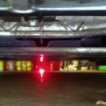

Notice in the photo above that it is easy to see a laser line showing all the way along the bottom of the chassis. This is our tool for finding the center line. Notice also that there is a line along the garage floor. This is our tool for finding the center line when we are doing the toe measurements. The lines on the chassis bottom and on the floor have to be lined up, which is why we need to make sure the laser level is flat on the floor.
Now we will need to carefully line up the laser line along the bottom of the chassis to some reference points. There must be at least one at the rear of the car and one at the front. There are a number of useful points:
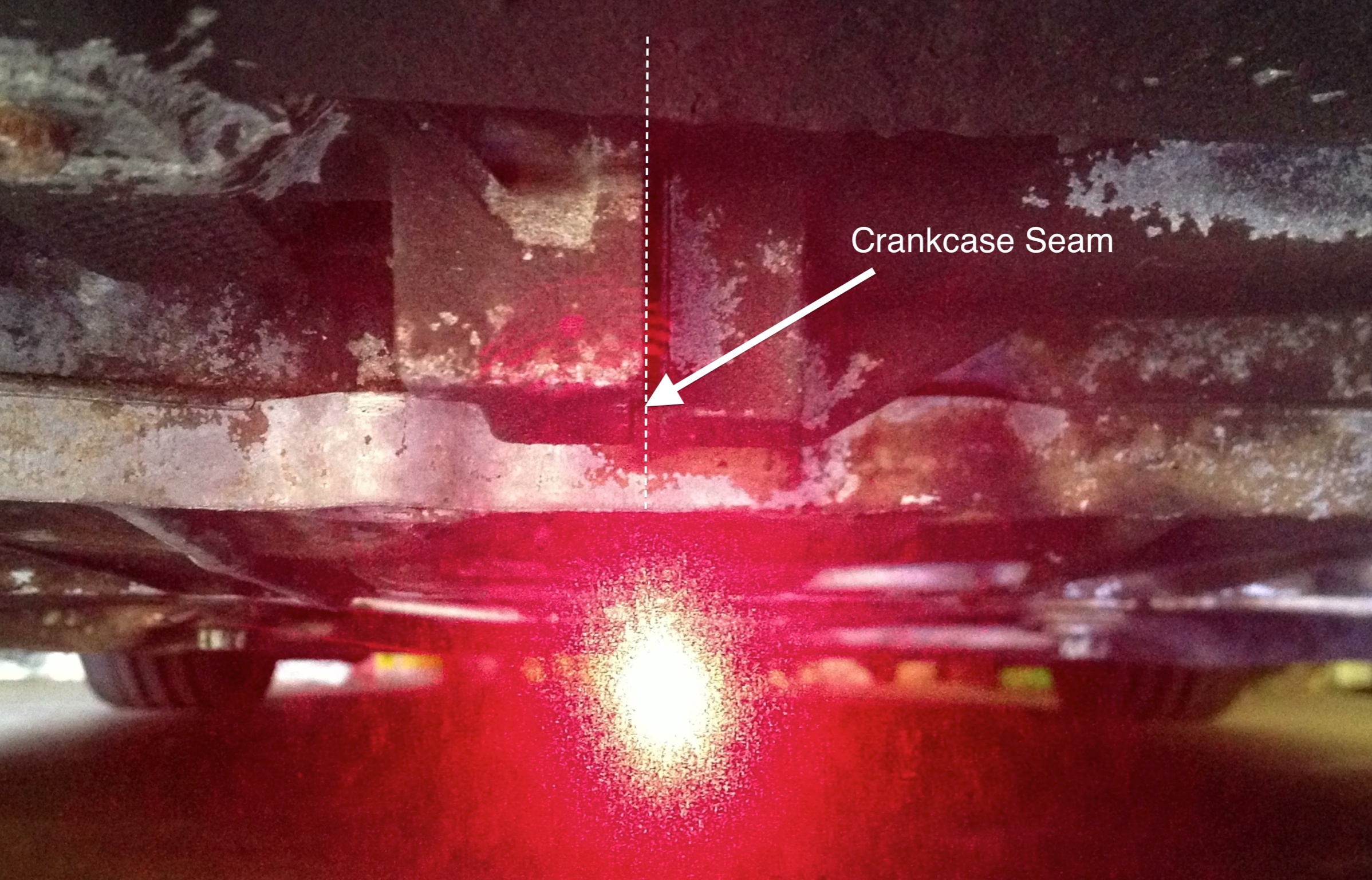
- In the rear, the crankcase seam, shown below (with laser light showing it’s precisely lined up with the seam):

- In the front, a screw at the center of the bottom of the front bumper cover attaching it to the chassis
- In the rear, a point marked exactly between the points where the two diagonal control arms of the rear suspension attach to the suspension subframe. This location needs to be marked in some way that is easy to see against the laser line passing by it (a Sharpie would do).
- In the front, a point marked exactly between two symmetric suspension components of the front suspension. Use your judgment and what you find easy to measure accurately and get a Sharpie in to mark accurately. Ideally use two components that are directly attached to the chassis, in other words do not move with the wheels and are not located with ball or other joints.
Numerous other points exist that are probably less reliable, such as patterns in the underbody coverings. I would not recommend using these as being even 2-3 mm off center puts our toe measurements at risk of being out of spec range.
It is worth spending the time getting this right. The placement of the laser forms the basis for all the toe measurements, so it must be as accurate as possible. Within 1-2 mm of the true center at both front and rear should be the goal.
Make sure the laser will not be disturbed for the remainder of the toe measurements by errant pets, kids, spouses, etc.
When you think the center line is precisely marked, check it one more time just to be sure.
Making the Toe Measurements
With the laser level set on the floor and shining down the center line of the car, we are ready to make the measurements.
Place Tape Measure For Toe Measurement
I made my measurements pointing to the rear of the car, so I put the tape measure behind the wheel I was measuring. They can be made pointing to the front as well. The only difference will come when entering this into the spreadsheet and instructions say what to do.
Decide where you will place the tape measure for the measurement, but don’t put the tape measure there yet. If measuring the rear wheels, I recommend placing the tape measure about 10-15 feet behind the rear wheels. If measuring the front wheels, the limitation will probably be that the pencil beam from the level won’t clear the rear tire, so the tape measure will need to be just in front of the rear tire. (Reverse the above if you are measuring by pointing the laser forwards; I pointed it backwards.)
Use the tape measure to measure the distance from the center of the wheel being measured to where the tape measure will be placed for the actual toe measurement. This measurement is not very critical; within a few inches is good enough accuracy. Write this measurement down; it will be one of the spreadsheet entries.
Unroll about 4-5 feet of tape measure and lock it. Slide the tape measure underneath the car where you measured the distance from the wheel in the step above. Watch the tape measure’s end to see when it crosses the laser line from the laser on the ground. Locate the tape measure’s end so that the tip is just barely in the laser line. The end of the tape measure is now exactly on the car’s center line!
Ensure the tape measure’s blade is vertical so that the beam from the laser on the wheel will hit the flat part of the blade and make it easy to read the blade markings where the beam hits it.
Also ensure that the tape is oriented straight right-to-left (matching the axles) and not at a skew angle.
Attach Laser Level to Wheel
Attach the angle bracket made in Part 2 to the wheel being measured using a bungie cord or something similar, so it is pointing right onto the tape measure blade. Specifics will depend on the wheel and spoke design. Place the second laser level (the one that stays in “pencil beam” mode) in the angle so it is directly resting at all points on the angle. Ensure the laser level is firmly held and there are no screws, nuts, irregularities or any material stuck between the level and the angle. The laser level must be contacting the rear face of the angle at all points without any gaps. (It might be necessary to file off a little bit of the laser’s plastic slider in front). See the photo below.

In this photo the right rear wheel’s toe is being measured. The laser level is in the angle bracket and in the distance, about 10 feet behind, the tape measure is lying on its side. The tip at the very end of the tape measure (not visible) is just in the center line laser’s beam. The red laser dot should be easily visible on the tape.
Adjust the angle/level a bit so the pencil beam hits the tape measure blade. Ensure that the angle touches the wheel rim firmly and evenly without any gaps or play.
Check everything for tightness once more.
Make the Two Toe Measurements
Now walk to the tape measure and read off the distance where the laser beam hits it. In my case, the measurements were normally in the range of 87 -91 cm (my tape measure has mm markings and cm labels). Write down the measurement.
Go back to the wheel, and flip the laser level over. Some minor readjustment will probably be needed to get the beam onto the blade again. Ensure firm contact of the angle against the rim and the laser level against the angle.
Walk over to the tape measure again and read off the distance where the laser beam hits it. It will be different from the first measurement, by possibly as much as 3 cm. This is OK.
If you are confident of the quality of these two measurements, proceed to the next step. If not, it is very easy to go back and redo these two measurements.
Reference Measurement
We have one more measurement to make: the distance reference of where the laser itself is located from the center line. It is the difference between the laser location and the location of its beam measured in the step above that will give us the toe.
The task here is to measure the distance of the laser beam as it leaves the level from the center line. This has to be done to the same accuracy as all the other critical measurements. We will need to do it in two steps:
- Move the tape measure so that its blade is directly underneath the laser hole in the end of the laser level, and do the same work to put the tip of the end of the tape measure just barely in the laser center line, just like in the previous measurement
- Use a bubble level or similar to drop a perfectly plumb line down from the laser beam right at the point it leaves the level to the tape measure, and read off the distance shown on the tape measure
Write down the distance from the measurement. This is the final measurement to be entered in the spreadsheet to calculate the toe.
At this point don’t read much into whether the distance to the center line is less than greater than the distance measured previously. The camber angle and the distance between wheel and tape measure in the first measurement set interact with the distances here and it is not obvious which way toe will actually be calculated yet.
Finished With One Wheel, Now Do the Rest!
Although the instructions for setting up and making the measurements are fairly long, they go quickly. Center line setup takes maybe 5-10 minutes, and each wheel takes 5 minutes when practiced. All four wheels will take less than 1/2 hour with some experience.