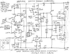
Hafler SE240 Power Amplifier Schematic Diagram
Schematic Diagram
For the hordes of Hafler fans out there dying to get a schematic diagram of the SE240 power amplifier, here it is.
This schematic is (obviously) hand drawn based on reverse engineering the circuit board. It shows only the key parts (active signal path) of the right channel, but it’s most of the components of the channel. Input switching and RC network is not shown, and most supply bypass caps are not shown (there aren’t many). All elements of the signal path are shown.
While a few sources found in web searches indicate that the SE240’s circuit is similar to the DH220 kit, which has schematics easily available, it is only partly so. There are quite a few important differences, such as an all-FET input stage with cascode isolation, thermal sensing, input stage switching to support bridged mode operation, and no speaker fuse.
I drew this schematic to diagnose a massive overheating problem which appeared to be due to uncontrolled oscillations (the 10 ohm 5 watt resistor in the speaker output path was smoked). I thought the cause would be a cap in the feedback loop having gone bad, causing loop gain at 180 degree phase to be above 1. In the end, it wasn’t any such cause; it appears that simply having disconnected the power connector and the fuses restored the amp to perfect working order, and it sounds fabulous again.
Key Properties of the SE240 Circuit
Key properties of the SE240 circuit:
- All FET input stage: MOSFET to drive the positive rail, JFET to drive the negative rail. Unfortunately specs for the MOSFETs (2SK163) appear to be impossible to find.
- Cascode-based isolation of input devices from the full rail voltage, and to improve input stage bandwidth
- Thermal sensing and shutoff by reducing bias current of input stage
- Input switching to support mono (bridged) operation (not shown in schematic)
- No speaker protection fuse
- Two high-gain voltage gain stages, followed by two follower-based current gain stages including the output FETs; overall a non-inverting amp
- Low-band gain of 1 (below 0.1 Hz) rising to midband gain of 26.4 at 2.3 Hz
Adjusting the Output Bias Current
While I was in there I adjusted the output stage bias current:
- Turn off and unplug the amp! Remove input and speaker connections
- Remove one of the supply fuses
- Install an ammeter in the fuse’s place (make sure cables are hooked up to ammeter plugs!!)
- Plug in and turn on the amp
- Adjust the bias pot so the ammeter reads 200 mA (I am guessing at this value; I’ve seen people describe settings between 150 and nearly 300 mA). At 200 mA the amp dissipates 26 watts in quiescent mode, which gets it nice and warm but not hot.
- Turn off and unplug amp
- Replace the fuse
Replacing Capacitors
I also ordered a set of replacement capacitors for the signal path and bypass caps from Mouser Electronics where I was pleasantly surprised to find all items in stock and at quite good prices, even including Nichicon capacitors. Note the original capacitors are polycarbonate film which is for all practical purposes no longer available (discontinued in 2000), and a good replacement for audio applications is polypropylene film. The complete set cost under $30 including shipping.

Paul
/ Sep 8, 2023Hey is the pro2400 the same as the se240 ?
Ricardo (Madrid, Spain)
/ Feb 16, 2017I’ve found this schematic very useful. I have to fix my old SE240 Hafler power amp, but I cannot find the values of two burned resistors, marked at PCB as R24 and R59 (left and right channels), one of them it’s broken and the other measures 24?, but the colour of the stripes are changed, may be the value is 18? or 100?
Somebody can help me with this?
Curt_C
/ Feb 9, 2015Nicely done, Mike.
Looking at your drawing it looks nearly identical to the PRO2400 schematic, but without the balanced input and level control board. The PRO2400 manual is available on HiFi Engine.
C
DavidT
/ Nov 24, 2014Thank-you for your patience and effort to trace-out the 240 schematic. It is very helpful. (and tedious, I know!)
It seems the 2SK163 could be a JFET, which is used sometimes instead of the trusty 2SK170 as a complement to the 2SJ74, when a higher working voltage is required.
The 2SK1636 often shows up in a search as a 2SK163, with the final “6” dropped for some reason. The 2SK1636 is , indeed, a medium power MOSFET; but this would be unusual in a symmetrical and balanced diff input stage…
The 2SK163 JFET can be purchased here, as of 11/24/2014:
http://www.ampslab.com/components_fets.htm
Thank-you for sharing the 240 schematic, and hopefully this note helps you, as well as those who land here…
Kind Regards,
David
VittorioC
/ May 10, 2015It is confirmed that 2SK163 is a JFET. If somebody is still looking for the datasheet, he can find it here:
http://www.datasheets360.com/part/detail/2sk163/-2713613957636864927/